Pond Float Switch Wiring Diagram

How To Install Float Switch Wiring And Control Diagram Water Pump Motor Automatic On Off Youtube

Septic Pump Float Switch Wiring Diagram Tank Fresh Amazing Gallery The Best Electrical Circuit 7 Septic Tank Float Electrical Installation
Pond Pump Float Switch Pond Equipment Forum Pond Life

Float Switch Wiring Diagram For Water Pump Youtube

Ls72dbzrs3ic0m

Float Switch Wiring Schematic Diagram Lovely Septic Tank Pump 0 3 Way Switch Wiring Jet Pump Diagram

The second schematic shows how a pump up to 2hp can be wired for proper operation.
Pond float switch wiring diagram.

Water Well Pressure Switch Wiring Diagram Gooddy Org New Webtor Me And Well Pump Submersible Pump Submersible Well Pump
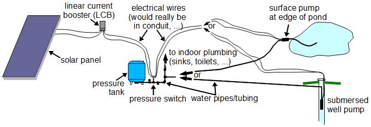
Solar Pumping
Pond Cabin Water System Terry Love Plumbing Advice Remodel Diy Professional Forum

Amazon Com Marine Boat Bilge Pump Float Switch 12v 24v 32v Ignition Protected Mercury By Sailflo White Sports Outdoors

Single Ball Float Switch Wiring Diagram Bosch Dishwasher Water And Remarkable Septic Tank 11 Submersible Well Pump Well Pump Pressure Switch Well Pump

Pump Float Switch Wiring Diagram With Schematic On Level B2networkco For Dual Septic Tank 6 9 Well Pump Pressure Switch Submersible Pump Well Pump
Pin On Plumbing

Installing Float Switch To Bilge Pump Page 1 Iboats Boating Boat Wiring Boat Restoration Boat
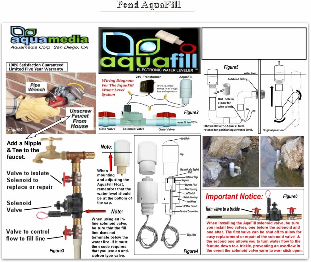
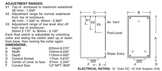
Pond Auto Fill Water Level Controllers Aquafill

Wiring A Float Switch With Rps Solar Pump System Rps Solar Pumps America S 1 Solar Well Pumps

Using A Pressure Switch With Your Solar Pump Rps Solar Pumps America S 1 Solar Well Pumps

Float Switch Controlled Water Level Controller Circuit Circuit Projects Circuit Floating In Water

How To Wire A Bilge Pump On Off Bilge Switch New Wire Marine Boat Wiring Boat Boat Battery

Basement Watchdog Combination Primary Pump And Backup Sump Pump Model No Dfk961 Installation Diagram Backup Sump Pump Basement Watchdog Sump Pump

Flyingfishq Diagram Float Switch
Another Diy Rdf Project

Using Batteries With Your Solar Pump Rps Solar Pumps America S 1 Solar Well Pumps

2359 Wire Lead Float Switches For Sump Pumps Septic Tanks Water Tanks Sump Pump Septic System Water Tank
Https Encrypted Tbn0 Gstatic Com Images Q Tbn 3aand9gctg4e5duv52v8tktfyf Y4uvoa5zdx Lcxl5cbf1i9obyy9ghvh Usqp Cau

Float Switch Wiring Float Switch Level Switch Installation For Water Tank By Evergreen Electrical Youtube

Aquarium Auto Top Off System Marine Magic Dual Ato Ad Top System Aquarium Neptune Systems Aquarium Sump Aquarium

Free Shipping Df96d Ac220v 5a Din Rail Mount Float Switch Auto Water Level Controller With 3 Probes Control Panel Switch Horncontrol Aliexpress
Pem L104 46 Wall Mounted Water Level Sensor 463 0700 Coastal Fountain Supply Leading Wholesalers Of Commercial And Residential Pond And Fountain Equipment Tucker Ga 770 496 5740 Authorized Pem Distributor
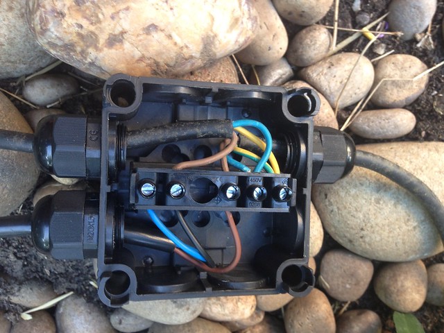
How To Hard Wire A Float Switch To A Submersible Pump
Source : pinterest.com
