Ptc Sheet Metal Flat Vs Flange

Challenge Modeling Complex Curved Sheet Metal Flan Ptc Community
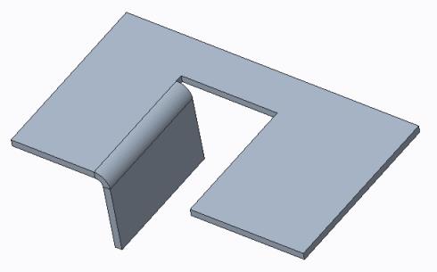
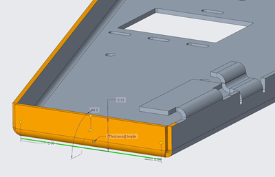
About Attached Flat And Flange Walls

Tutorial Sheet Metal Conversion Two Examples Ptc Community
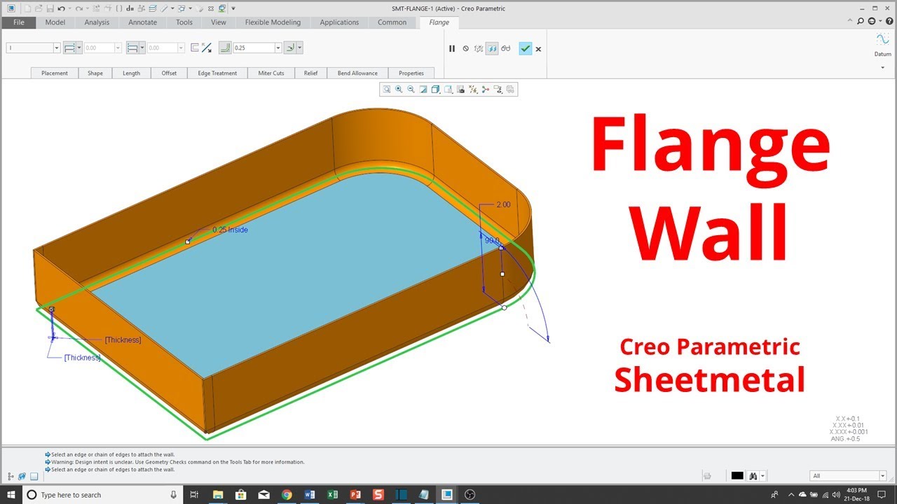
Creo Parametric Sheetmetal Mode Flange Wall Youtube

Creo Parametric 6 0 Sheetmetal Flat And Flange Wall Changes Youtube

Flange All Types Command In Creo Sheetmetal Youtube

Flange is improved in sheetmetal design.
Ptc sheet metal flat vs flange.
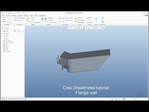
Creo Sheetmetal Tutorial How To Create Flange Wall Feature Youtube
About Bend Relief

Engine In Creo 3d Modeling Tutorial Parametric Mechanical Design

Pin On Solidworks

Waht Is The Difference Between Flat Wall And Flange Wall Youtube

Unfolding Onshape Sheet Metal

Flange Is Improved In Sheetmetal Design Youtube
Enhanced Productivity And Usability When Working With Wall Features

Pin On Solidworks

Pin On Solidworks

Solidworks Sheet Metal Tutorial Hopper Youtube In 2020 Sheet Metal Drawing Sheet Metal Metal Sheet Design

Pin On Architecture

Bending Short Flanges Metal Working Tools Sheet Metal Tools Metal Bending

How To Add Sheet Metal Gusset In Creo Pro E Users Ptc Creo Grabcad Groups

Solved Bend To End Of Surface After Flanges Ptc Community
About Standard Flange Wall Shapes

Joist Hangers For Bunk Bed Google Search Deck Railings Deck Rail Bracket Railing

Closed Section For Bend Relief
Https Encrypted Tbn0 Gstatic Com Images Q Tbn 3aand9gct3zfazig75npdzpw Xd R1gzsyacdxiq4uba7vtl4pdytnncyc Usqp Cau

New Edit Corner Relief Tool Youtube
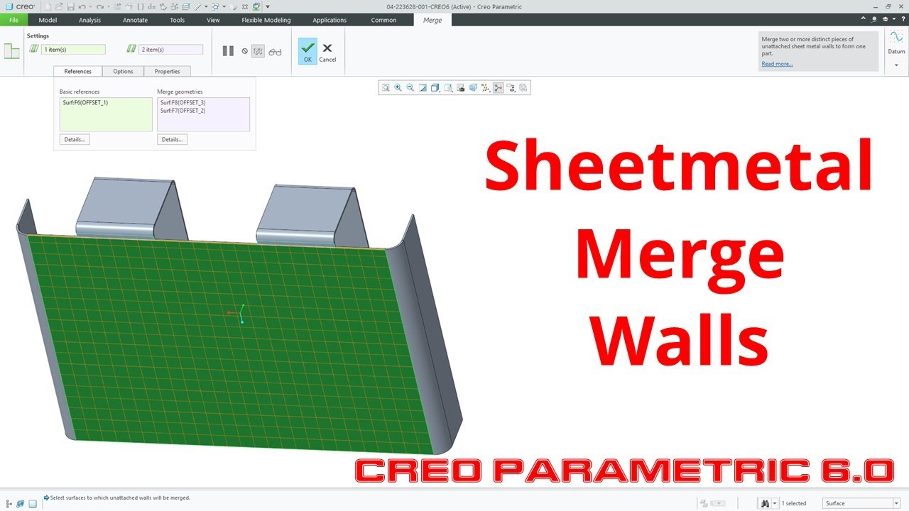
Creo Parametric 6 0 Sheetmetal Merge Walls Youtube

Onshape

Pin On Inconel Alloy 625

Solidworks Panosundaki Pin
Source : pinterest.com
